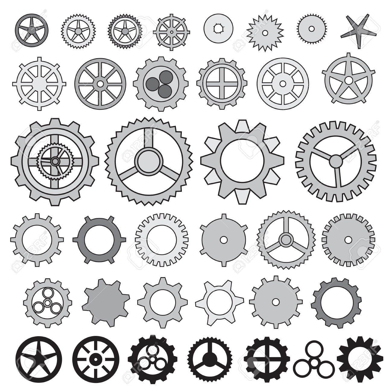
Mechanical Gears Drawing at Explore collection of Mechanical Gears Drawing

Simple Gear Drawing at GetDrawings Free download
Don't miss my: Autocad - Exercises for beginners Step by Step.https://youtube.com/playlist?list=PLe_I-JWckL7FKZZa0q9e9cRQh8bEDlZnDExercise to make a Gear in.

technical drawing gear Autocad Drawing, Technical Drawing, Mechanical Design, Mechanical
Various drawing output functions for KHK Stock Gears. When a new gear is needed in a customer's machine design process, it is very time-consuming to design a new gear as well. In order to save you time and effort, KHK Stock Gears provides you with as many as 30,000 pre-designed gears as standard gears, and for each KHK Stock Gear, we provide.
Gear Drawing at GetDrawings Free download
1. Start with the gears effect included in Inkscape. Visit the Extensions tab, then go to Render and then Gears. Adjust your gear's parameters in the pop-up window, and click "Apply" when done. Be sure to check the "Live Preview" box to see the effect of your parameter changes in real time.
Gear Drawing at GetDrawings Free download
Please turn on the captions for extra instructions!Hi everyone, I wanted to make a video about drawing out functional gears with a compass. It goes over the.
Gear Drawing at GetDrawings Free download
By having these tools at hand, you'll be able to draw gears confidently and consistently while making the process smoother as well! How to Draw a Gear: Step by step. Step 1: Draw circle. Step 2: Add small circle. Step 3: Make tooth of gear. Step 4: Add more teeth. Step 5: Erase guidelines. Proportions and Drawing Tips
Mechanical Gears Drawing at GetDrawings Free download
Lets start with a gear tooth size of 10 mm I want a gear with 5 teeth on it so the circle will be 10 x 10mm round (circumference)= 100 mm To draw that circle I need to find the diameter so I use a bit of maths and a calculator a divide the circumference (100 mm) by Pi = 3.142 This gives me a diameter of 31.8mm I can draw this with a compass and.

How To Draw a Gear Step By Step For Kids YouTube
How to Use a Spur Gear Generator. Input the following parameters in our free gear dxf generator: Tooth Count - is set with the parameter "n" for Gear 1 and Gear 2. Gear Type - External spur gears use a positive tooth count, while internal spur gears use a negative tooth count. For a rack and pinion, set n=0.

Pin by Blair Long on Ideas de Cumple 2 Maker fun factory vbs, Maker fun factory vbs 2017
Gear drawing is an essential skill for designers, engineers, and artists alike. Whether you are creating a mechanical design, designing a game character, or simply expressing your creativity through art, understanding the basics of gear drawing is crucial.

GEAR DRAWING how to draw gears by hand YouTube
Using your ruler, draw the first tooth of the gear by connecting the intersecting lines created in step two. Step 4: Continue Drawing Teeth. Repeat step three, drawing the remaining teeth until your gear is complete. Step 5: Add the Center Hole. Draw the center hole of the gear by using your compass to create a smaller circle in the middle of.

Simple Gear Drawing at GetDrawings Free download
#engineering #tutorials The involute gear profile is the most commonly used system for gearing today, with cycloid gearing still used for some specialties su.

Simple Gear Drawing at Explore collection of Simple Gear Drawing
Designing and drawing involute gears in a CAD program is tricky, but if you follow the steps below, the teeth will come out right every time. Go slowly and make sure that you follow each step carefully, and soon you'll have a great gear ready for print! Step 1 . Calculating involute gear tooth geometry starts with understanding the number of.
Gears Drawing at GetDrawings Free download
1. Pick a start point and draw upwards 1/2 of the pitch, and out to the right some distance (longer than expected gear radius). 2. Rotate the line extending to the right up an angle of [360deg / (# Teeth * 2)]. 3. Draw a line from the upwards extending line to the intersection of the angled line. 4.

Gear Drawing Free download on ClipArtMag
Step 6: 6) Draw a construction circle through the centre and the point found in the previous step. This circle is the base circle for the involute. As you may know, an involute is the curve described by the end of a string wound around a cylinder. And the "string length" is the distance shown in the next step:

Gear, mechanics, or settings illustration. Doodle style gears, cogs, or settings , sponsored,
Beside the premade gear templates, there is also an option to draw custom gear designs, such as a custom involute gear, using eMachineShop CAD Design Software. It is important to save gear designs in format that allows for dimensional accuracy when sharing or manufacturing the part. Popular file formats for gear designs are STEP, STL, IGES, DXF.

Gr8 Technology Whirligigs patterns, Gear drawing, Technical drawing
Draw the base circle of one gear (since the gear ratio is 1:1, we only need to draw one). Create 5 equally-spaced segments that extend from the center of the circle to it's outer circumference Draw a chord (a line whose endpoints lie on a circular arc) from a point of intersection (between one of the radial lines and circle) to the furthest point
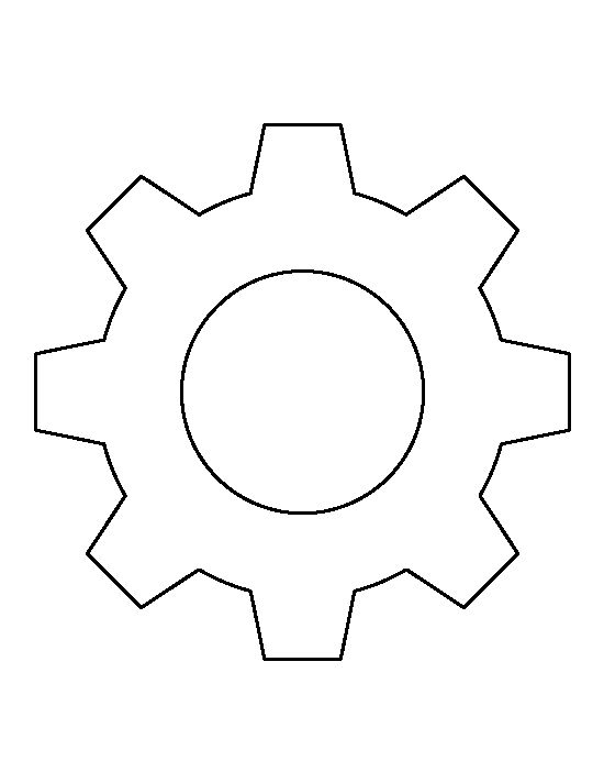
Simple Gear Drawing at GetDrawings Free download
How To Draw a Gear Step By Step For Kids
